Linax Technologies, Ltd.
In the history of radiotherapy, one of the first engineering problems was that of obtaining a high energy photon beam that was capable of deep penetration into tissues and superficial tissue sparing. After the development of hot cathodes by Coolidge in 1914, there was considerable effort made in producing high energy x-ray tubes. In the 1920s and 1930s, x-ray “cannons” were developed that had high energies, with one unit having a peak voltage of 1000 kVp, installed at the Swedish Hospital in Seattle. These units were difficult to operate, and the method of using a single acceleration potential for radiotherapy was not viable. Other machines, including the Van De Graff accelerator and Betatron were invented, and could produce megavoltage x-ray beams, but these devices proved to be difficult to operate in a hospital environment, and were eventually replaced by the much simpler cobalt teletherapy units. Cobalt teletherapy was a work horse of radiotherapy for about 30 years, however the need to create an electronic means of megavoltage photon beam production, one that did not rely on radioactive sources, eventually led to the development of the linear accelerator. Creating a high energy beam in a hospital environment, where space and access to the appropriate technology is more difficult than in a laboratory environment or high energy physics environment is not a straightforward task, and many technological problems had to be overcome in order to solve this problem.
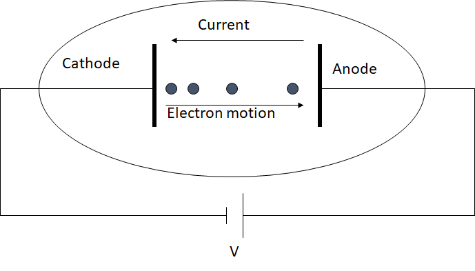
X-ray tubes use a direct acceleration method to produce a high energy electron beam. The method, shown in Figure 1, has a practical upper bound of about 0.5 MeV, after which, dielectric breakdown and electron arching problems make it impractical. As well, at larger acceleration energies, the electrical components required for direct acceleration become non-proportionally large, making this approach unsuitable for clinical applications, where systems must be installed in a hospital environment. It is possible to use a staggered approach concurrent with direct acceleration, where several cathode and anode stages are mounted in series using a single power source. However, this solution is also impractical in that the control circuits required to switch the applied high voltage to alternate accelerating plates can be very complicated since the electron transit times are very quick, and that considerable power must be passed through high voltage switches.
The solution that has been employed in linear accelerators is to use microwave power in a suitably designed waveguide such that an electric field is created that can accelerate charged particles to high energies. In a suitable designed waveguide with a corresponding microwave field and sufficient power, energy can be effectively transferred from the microwave field to the charged particles (in our case these are electrons). As an example, a cylindrical waveguide operating in a TM01 mode has an electric field pattern similar to the one shown in Figure 2.
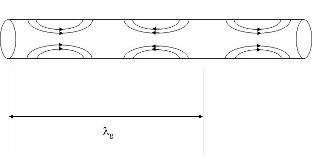
The electric field pattern originates for the waveguide walls, and is oriented such that part of it is parallel with the central axis of the waveguide. This portion of the electric field is therefore useful for electron acceleration in that if the electrons were suitably positioned so as the see the accelerating field, they could be accelerated in a direction that was not physically blocked by the waveguide. There is one important problem with this arrangement, which is that the speed electrons would have to travel to become attached, or bound, to the microwaves, is greater than the speed of light for energies, sizes and frequencies that are used in radiotherapy linacs. As an example, for a cylindrical waveguide with diameter 10 cm being excited by microwaves of frequency 3 GHz, the guide wavelength, lg, is about 14.1 cm. The cycle time for this wave is 1/3GHz, or about 0.33 ns, and so the velocity that an electron would have to travel to continually see a positive electric field is the guide wavelength divided by the cycle time, or about 4.2 x 10⁸ m/s, or about 40% higher than the speed of light. This is a problem in that a simple cylindrical waveguide such as the one above cannot accelerate electrons since the electrons can never reach the required phase velocity due to their upper limit of the speed of light, and so the electrons cannot become bound to the accelerating microwaves.
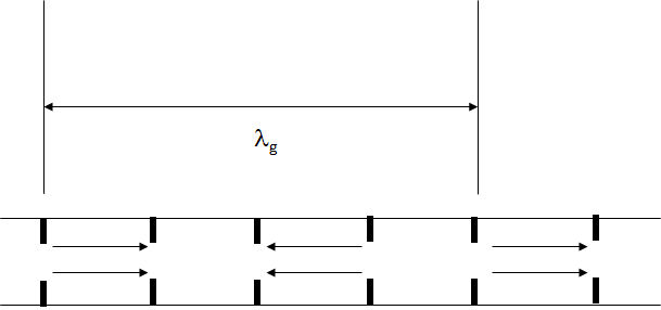
It turns out that when building linear accelerator waveguides, the engineer has a lot of freedom to change the internal shape of the waveguide without affecting the basic waveguide propagation mode. As an example, the waveguide above can be adjusted by adding spacers with holes in them, called irises or septum, as shown in Figure 3.
By introducing these septa, the waveguide designer has quite a bit of control over the microwave field, and the guide wavelength in particular. In fact, for the waveguide discussed above, the guide wavelength can made to be 10.0 cm, and so the phase velocity then becomes 3 x 10⁸ m/s, which matches the speed of light, and electrons are now able to bind to the microwaves, and be effectively accelerated.
The waveguide design with periodically spaced septa, allows effective electron acceleration to high energies. The septum has the added benefit of concentrating the electric field near the axis of the waveguide, which increased the accelerating potential for a given length of waveguide. In the waveguide septum orientation shown in Figure 3, the septa are evenly spaced and the electric field pattern from the pure cylindrical waveguide is more or less reproduced, where there is electric field is concentrated in alternating cavities (for p/2 phase shift per cavity). Not shown in this diagram is the magnetic field orientation, which is dominant in the other cavities, where there is less electric field. Not only can the waveguide septum be used to adjust the guide wavelength, but for a given guide wavelength, the relative amounts of stored electric and magnetic energy can also be adjusted relatively easily by adjusting the position of waveguide septum. Figure 4 shows different septum orientation which increase the accelerating potential of the linear accelerator for a given accelerator length.
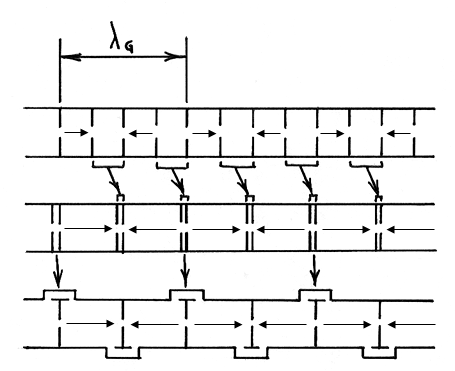
In Figure 4, the guide wavelength, lg, is the same for all three septum orientations, so the phase velocity will be the same. However, the cavities that have mostly magnetic energy have been changed in size in order for the cavities with electric field to dominate, and allow a greater length of the waveguide to be used for electron acceleration. In the bottom design, the magnetic field cavities have been removed from the axis of the accelerator altogether, and moved to the side, which is the standing wave side-coupled cavity waveguide design that is very common in radiotherapy today. These cavity dimension changes have two physical effects on the waveguide. Firstly, the resonant frequency, in the case of the standing wave accelerator, changes since this is the frequency where the electric and magnetic field energy density are equivalent. Secondly, the impedance of the waveguide is also changes. The microwave impedance is the ratio of the transverse components of the electric to magnetic fields. The impedance of a wave in free space is \(\sqrt{\dfrac{u_0}{\epsilon_0}}\), which is essentially the ratio of field strengths of an unconstrained wave (m0 and e0 are physical constants called the permeability and permittivity of free space, and are used to calculate electric and magnetic field strength). Within the waveguide, the wave in constrained, which affects the ratio of electric to magnetic field, and so the wave impedance is also changed. The waveguide shunt impedance is closely related to this concept
Most importantly, it is a measure of the ability of a waveguide to transfer energy from the microwave field to the charged particles, which are electrons for medical linacs. The concept of shunt impedance is one of the most important physical concepts to understand in understanding how SIMAC simulates linear accelerator since it turns out that the relationship between linac beam energy and beam current can be described very simply, using a linear relationship. This relationship can be quickly and easily calculated, making it possible to compute, even with low power computing, the response of a linear accelerator to changes in beam parameters. To understand the concept, consider the circuit shown in Figure 5.

In this figure, we show a simple series electrical circuit, with a power source, whose value is \(\sqrt{P_{KY}Z}\) , where \(P_{KLY}\) is the microwave power coming from the klystron or magnetron, and Z is the linac shunt impedance. The expression has units of Volts. The accelerator structure, \(V_{ACC}\) , is represented by a simple resistor, and the accelerator beam current, \(i_{ACC}Z/2\), is also represented by simple (variable) resistor. Solving for the value of \(V_{ACC}\), we obtain an equation that has the same form as the well-known beam loading expressions for linacs: \(V_{ACC} = \sqrt{P_{KLY}Z} - \dfrac{i_{ACC}Z}{2}\)
We arrived at this equation very simply. The technique used is known as “lumped circuit modelling” for linear accelerators. It can be simple, as we have done here, or the technique can be made very complicated and expanded to use capacitive elements to model electric field energy storage, and inductive elements to model magnetic field energy storage.
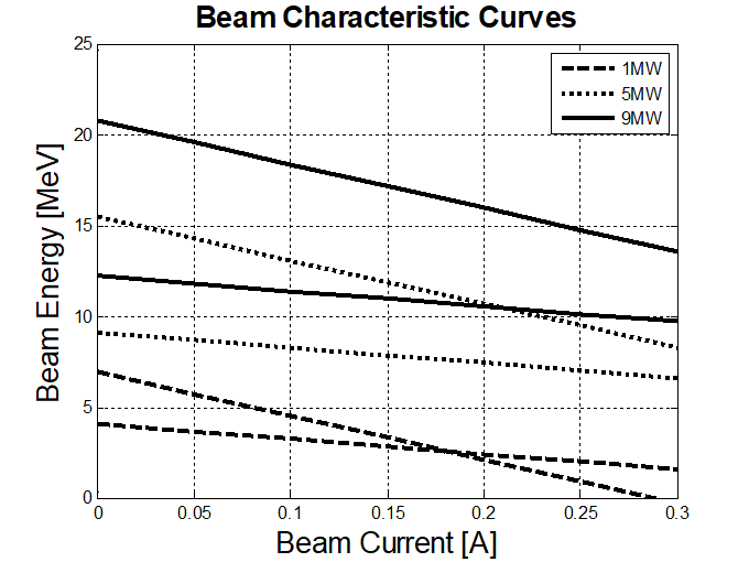
This method predicts that the accelerating beam voltage depends linearly on the beam current, with highest energy at zero current, and a linear decrease in energy with increasing beam current that depends on the linac shunt impedance. When plotted, beam energy – beam current relationships are shown in Figure 6.
When using the beam loading model, it is a fairly simple task to calculate the beam energy if the beam current and microwave power are known. In SIMAC, the idea is to use as simple physical model as possible in order to keep the computational requirements low for a real time calculation. For beam current and microwave power, we use two simple models, one for the linac gun (the electron source) and in the second, we model a klyston, which is an amplifier of microwave power.
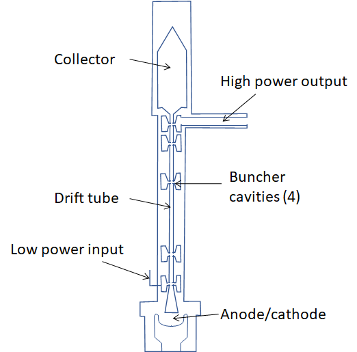
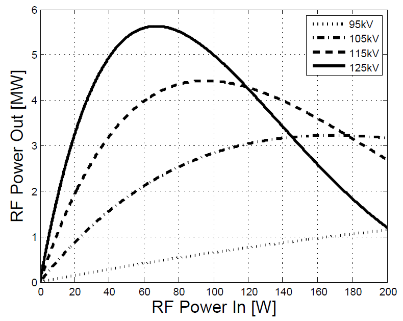
A klystron is a microwave device in which electrons drift along a drift tube going through a series of microwave cavities. A representation of one is shown below in Figure 7. In the first cavity a low power microwave field is injected. This field is arranged so that the electric component decelerates the electron beam. The deceleration is done so that the net effect is that the steady stream of electrons is “bunched,” i.e. electron velocities are reduced so that over a microwave cycle, the electron phase is narrowed. The electron bunches, when passing through subsequent microwave cavities, generate more retarding electric fields, which further enhance the electron bunching. The last cavity in the klystron is designed to have a large shunt impedance, so that the energy of the electron that drift through it is most effectively converted to microwave energy, which is then coupled out of the klystron to a transmission waveguide. The electrons, with their remaining energy are collected in a collector where they are stopped. This device can have gains on the order of \(10^{5}\), so that microwave inputs with power of about 50 W can be amplified to about 5 MW. The gain is dependent on the degree of bunching achieved in the device. Well defined bunches with a small spread in phase (over the microwave cycle) will produce higher output power. As the input microwave power is increased, the bunching effectiveness also increases, and a linear increase in power is observed. However, if the input microwave power is increased too high, the electron bunching can be negatively affected since the retarding electric field can push electrons over too wide a phase angle. The result is deterioration of the electron bunches, and reduced RF output power. The effect is known as “klystron saturation.” In SIMAC, this was modelled using Bessel functions, which have been found to reproduce the klystron saturation effect reasonably well for a two-cavity klystron. This modeling is shown in Figure 8, where the microwave amplification is plotted. As shown in this figure, the klystron saturation curve also depends on the voltage applied to the klystron cathode. It turns out that the maximum microwave power obtainable from the klystron at a given low microwave power input is linearly dependant on the cathode voltage applied. This relationship, along with the saturation curve is used in SIMAC.
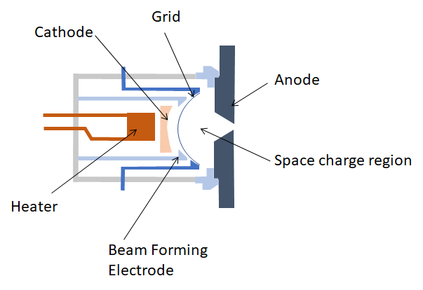
In order to inject electrons into the accelerating waveguide, an electron source is needed. In SIMAC, we modelled a Pierce-type electron gun. This type of gun is limited by space charge effects. An illustration of a dispenser cathode type of electron gun is shown in Figure 9. When these electron sources, or “guns” operate in space charge limited mode, electrons have to compete in order to fit through the small hole in the since electrons repel each other. “Space charge limited” means that the electron current that can be passed through the small anode hole is limited by the concentration of charge within the space charge region. This is very different from the “temperature limited” mode, where the current that can be passed through the anode is limited by the number of electrons emitted from the cathode, which depends on the temperature of the cathode.
For a type of electron gun as shown in Figure 9, if the grid is ignored, the Child-Langmuir law, which describes space charge limited mode, says that the beam current passed through the anode into the accelerator is proportional to the cathode potential to the power 3/2. $$i_{ACC} = pV^{3/2}$$
The constant p is known as the gun perveance. This relationship allows a simple means of computing the beam current entering the linear accelerator waveguide, and this is what is used in SIMAC. At present, SIMAC ignores the effect of a grid used in triode type guns. The grid allows space-charge to accumulate between it and the cathode, and can be modulated to release the space charge in a manner such that a precise amount of electrons can be injected into the waveguide. The perveance equation can be simply modified to account for this, however SIMAC does not do this in this version
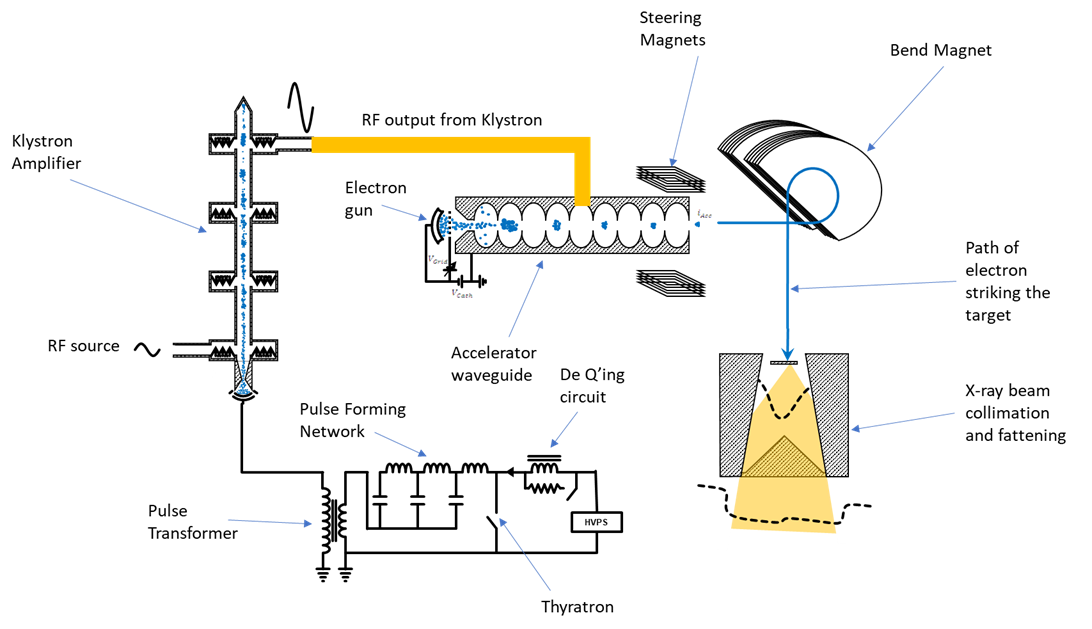
With the linear accelerator model (load line) and inputs of beam current (electron gun model) and microwave power (klystron model), we can model the electron beam that emerges from the linac base on voltages to the electron gun, klystron cathode, and microwave input power to the klystron. Many clinical linacs employ a bending magnet to redirect this electron beam towards the patient in order for the linac to be as small as possible since bending magnets can typically be built to have smaller physical dimensions that accelerating waveguides. A typical medical linac arrangement is shown in Figure 10
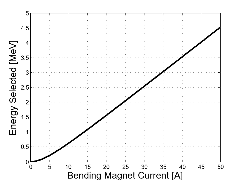
The bending magnet is modelled in SIMAC in a similar simplified fashion as the other linac components. The bending magnet is really just a dipole magnet which bends the electron path around the magnetic field. Assuming that this magnet behaves like a solenoid, we can model this quite simply. The result is a linear function between bending magnet current and pass through energy, as shown in Figure 11. The energy of electrons that emerge from the bending magnet and are directed towards the patient.
The last components to be modelled in SIMAC are the target and flattening filter, which converts an electron current on the target into a photon distribution in a water tank. This is an area where many medical physicists have good knowledge and understanding, and where there are many tools available to simulate this. For SIMAC, the important aspect is that that this model retain the real-time aspect of the program. In other words, one of the goals of SIMAC is to act like a real time simulator, which enhances the teaching value of the simulation package. Monte Carlo methods for dose transport through a target, flattening filter and water tank are computationally intensive, and very difficult to implement so that results can be displayed in real-time. SIMAC uses an analytical bremsstrahlung model which computes bremsstrahlung yield for thick targets (Findlay, Nucl. Inst. Methods. Phys. Res., A276, pp. 598-601, 1989). The model uses Kramer’s Law of photon yield, which says that the photon yield decreases linearly with photon energy, assumes a Gaussian distribution of scattered photons and electrons, and incorporates a photon attenuation within the target. With this model, and using mass attenuation in the flattening filter, accurate bremsstrahlung spectra can be calculated for target- flattening filter combinations used in modern radiotherapy. Photon beam flatness and symmetry can be computed for different electron beam angles and position of incidence on a target, as shown in Figure 12.
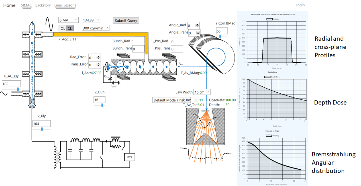
SIMAC is a linear accelerator simulator. It is a computer representation of how a medical linear accelerator functions. As a learning tool, it is hoped that SIMAC will permit a student to get hands on experience adjusting some linac beam parameters without having to have access to a real medical linear accelerator, or to worry about miscalibrating or otherwise damaging the accelerator. It can be used to understand beam steering, the effect of energy on beam flatness, how linac parameters affect beam energy and dose rate, and many other physical effects that are important in understanding the functioning of medical linear accelerators. It can also simulate “beam peaking,” which is a process that accelerator service staff often do after adjusting the linac or replacing important components. The user interface for SIMAC is shown in Figure 13.
Medical Linear Accelerators have two independent components when it comes to the electron beam current at the target. The first is the characteristics of the electron beam as it emerges from the accelerating waveguide. The second component is the bending magnet, which acts as a filter and lets electrons pass through which have a specific energy. The dose rate to the patient is maximum when the electron beam current is fully passed to the target, which happens when the electron energy produced by the accelerating waveguide matches the pass-through energy of the bending magnet. The principle of linac “Beam tuning” is to set up the operating parameters of the linac such that the electron energy gain in the waveguide is matched to the bending magnet current setting. In this sense the word “tuning” is different form the physical sense where a frequency is adjusted to match some resonant property. Rather it implies a matching of physical characteristics (the electron beam energies) of two distinct components in the linac.
Unfortunately, teaching beam tuning is not as easy we would like. The challenges for teaching this practice are that:
- There is a risk to damaging the accelerator if the electron path does not match the bending magnet path, and the electron beam strikes the wall of the bending magnet instead of reaching the target.
- In order to maintain operation of a medical linac, beam operating parameters can typically only be adjusted over a narrow range. Thus, there is little opportunity for a student to learn the macro effect of parameter and voltage adjustments since the range where the linac can operate is very small.
- The possibility that the clinical properties of the linac beam will change during a teaching session are real, and so appropriate quality assurance may be required after the training session, which can be a barrier to teaching.
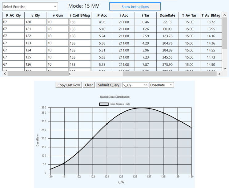
SIMAC has several beam tuning exercises, where the effect of parameter adjustment can be seen on dose rate, and the effect of changing a parameter over a large range can be observed and plotted. One of these exercises is shown in Figure 14.
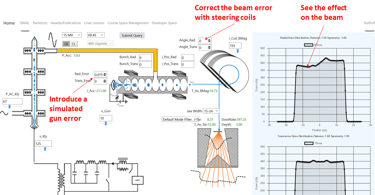
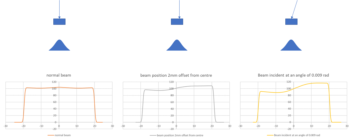
Beam flatness is an important part of linear accelerator quality assurance. SIMAC incorporates a simulation of the electron gun and steering coils. A beam fault can be simulated, and the effect on beam symmetry can be seen. The steering coils can then be adjusted so that the error can be corrected. This is shown in Figure 15.
The goal in using SIMAC is that students can learn how medical linear accelerators function in a constant and predictable environment, where the learning will not depend on the type of equipment that is available to the student, or the local access to this equipment. The full learning environment on the Linax.ca website includes a series of lessons, each focussing on a specific aspect of medical linear accelerator functionality. The focus is on relating the linac function to important clinical features of the linac’s radiation beam, with the hope that students will gain a better understanding of how to care for and maintain medical linear accelerators for radiation therapy.